Networks
Defining the network
Clicking the Define Network button opens the network configuration menu.
Initially, the system displays a simple one-line "network" with two boundaries:
- Boundary 1 at the outlet.
- Boundary 2 at the inlet.
From this starting point, users can add additional components as needed. Once the definition is sufficiently complete, the system sketch updates automatically.
Automatic network sketch
Most users already have a conceptual sketch of their system before beginning simulation. FlowlineProTT eliminates the need to manually redraw this sketch in the network definition menu. Instead, users simply define all lines, boundaries, junctions, and chokes, and the program generates the network sketch automatically.
At first, the network appears as follows:
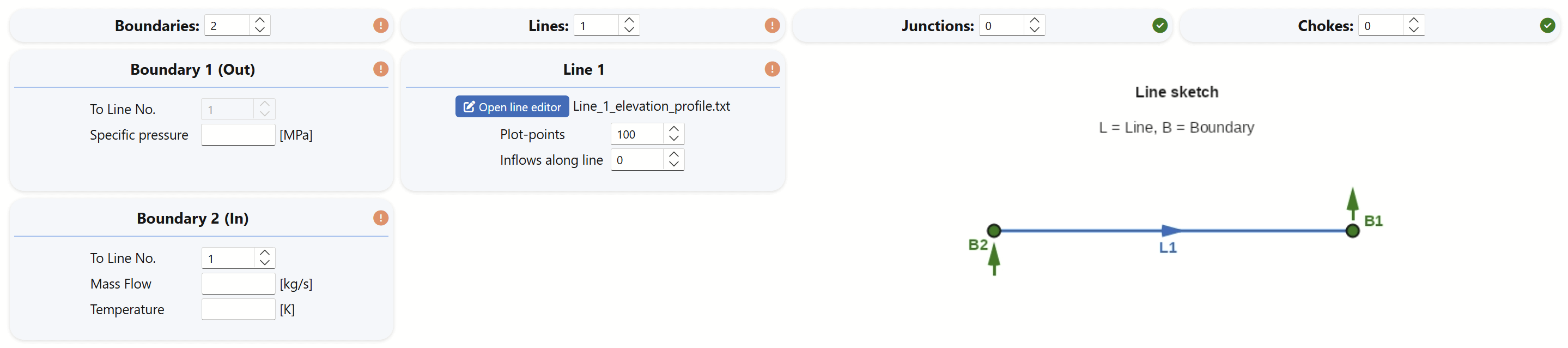
The default configuration consists of one line with a boundary at each end, and all system definitions start at this stage. This single-line diagram evolves as more lines, chokes, or inflow/outflow points are added.
Numbering the lines and boundaries
Defining the network follows some simple rules:
- The outlet boundary is always designated as Boundary 1.
- The line terminating at Boundary 1 is always Line 1, regardless of how many lines are added.
For simple single-line systems, users only need to specify:
- Inlet mass flow and fluid temperature at Boundary 2.
- Outlet pressure at Boundary 1.
- Basic line definition parameters, including diameters and elevation profile.
Building larger networks
Networks can be expanded by adding lines, boundaries, and junctions.
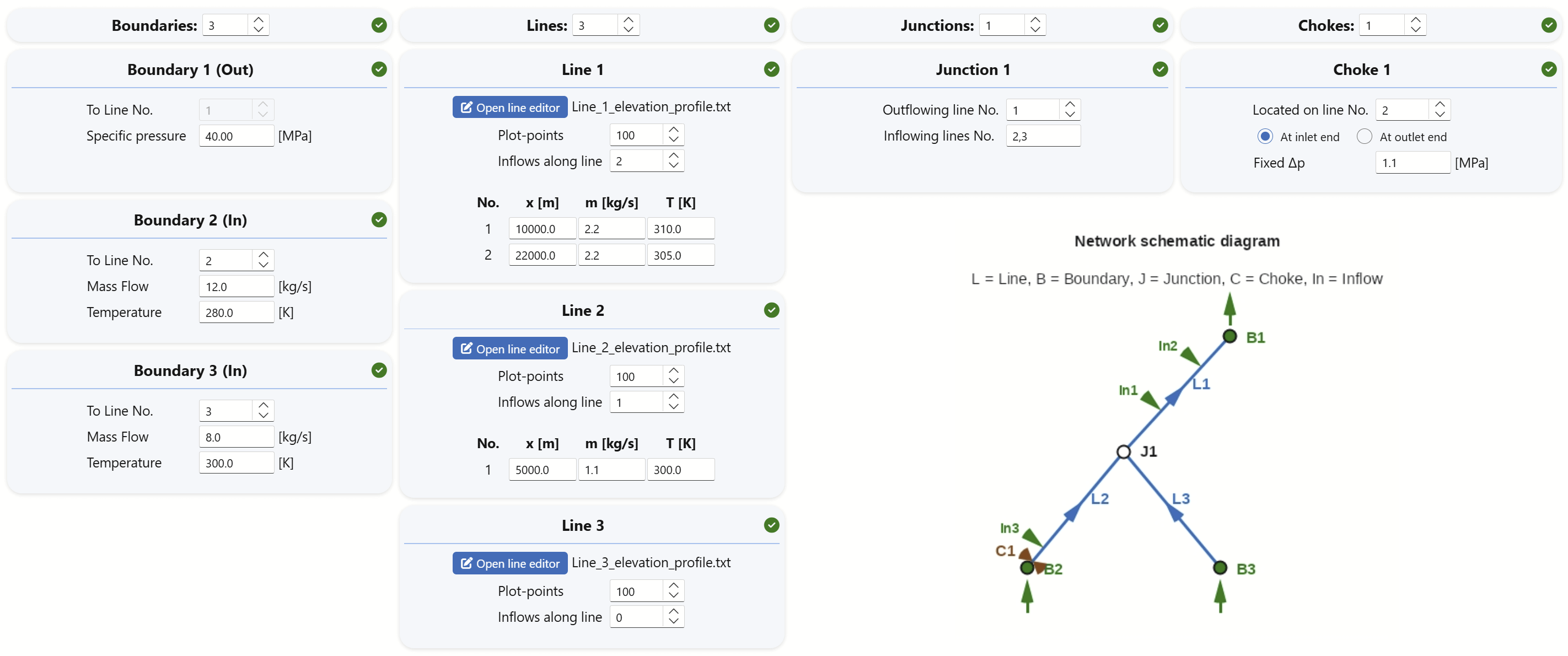
The figure below illustrates a configuration with:
- 3 lines.
- 3 boundaries.
- 1 junction.
Junctions can accept multiple inflow lines but must have exactly one outlet line.
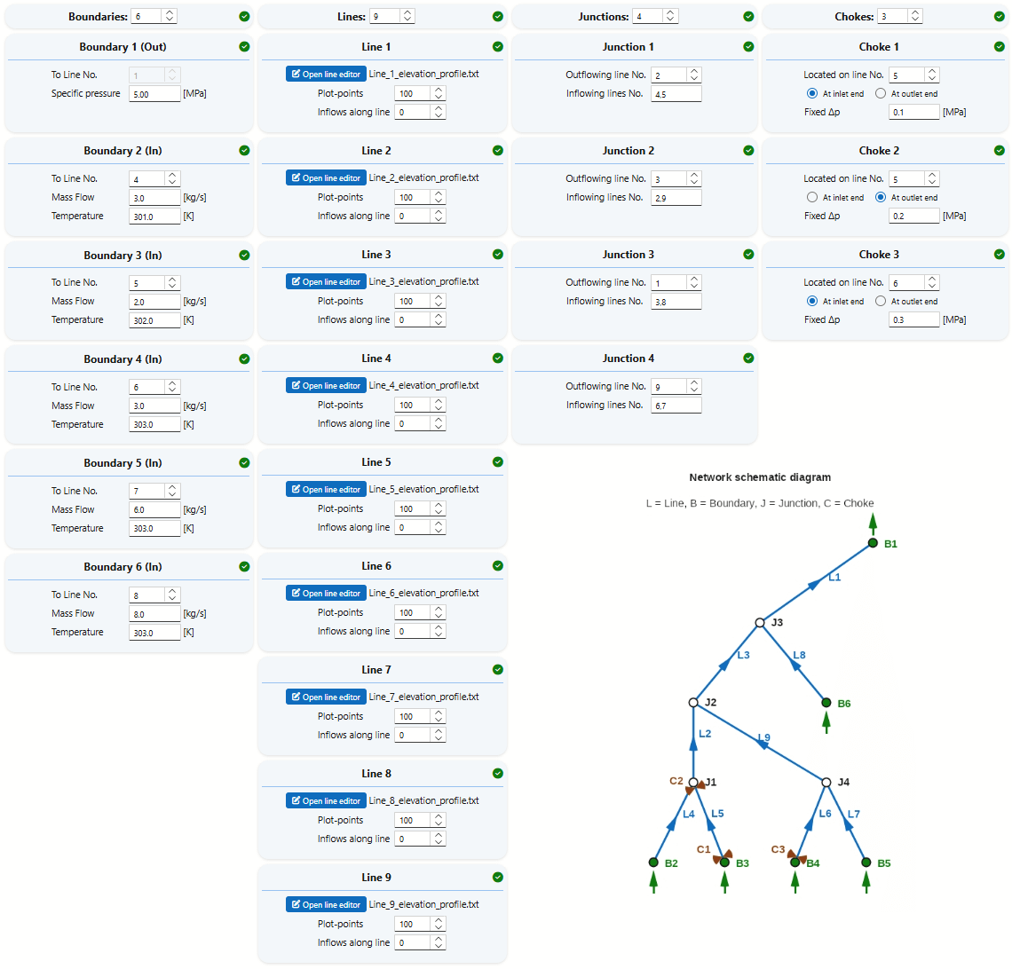
More complex networks may include additional lines, boundaries, junctions, and chokes. An example of a nine-line system is shown below:
Additional Line Input
The Line menu allows users to adjust the resolution of data saved along the pipeline by modifying the Plot-points parameter:
- Profile resolution: Specifies the number of data points used for plotting. Higher values yield finer detail without significantly impacting simulation time, though they increase file size (default: 100, but 1000 may be preferred for plots to be included in reports).
The Inflows along line menu enables the definition of perforation points or junction points, where connected lines simply are modeled as mass inflows into the main line:
- Inflow/outflow points: Indicates the number of locations along the line where fluid enters or exits (default: 0). Use negative values to define outflow points.
Example Configuration
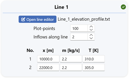
In the illustration above:
- At 5,000 m from the inlet, 50 kg/s at 300 K enters the line.
- At 15,000 m, an additional 10 kg/s of cooler fluid is injected.
Definition methods
By strategically placing inflow and outflow points along a single line, users can model complex networks with minimal setup.
- Multiple outlets—simply assign a negative inflow at each additional delivery location.
- Turndown and slug-limit curves are applicable only to single-line configurations.
- Flow regime plots for individual lines can still offer valuable insights into local flow behavior.
- Simplifying the network into a primary line with defined inflow or outflow points can be an effective strategy. This approach enables access to the more advanced slugging analysis tools within FlowlineProSS.
Locating chokes
Chokes can be placed only at line inlets or outlets. This design choice simplifies system definition in most cases and does not limit modeling capabilities.
- Split the line into two segments at the desired choke location.
- Insert the choke at one of the line ends at the junction between the two segments.
Network definition summary
- All network ends must be defined by boundaries.
- Line 1 must always connect to Boundary 1 at its outlet end, and the outlet pressure must be specified there.
- All boundaries except Boundary 1 are inlets, requiring both mass flow and fluid temperature to be defined.
- Each junction must have one outlet, but may have multiple inlets (minimum of one).
- Additional inlets or outlets can be defined at any point along each line.
- Chokes with defined pressure loss can be placed at line ends. Other placements can be created by splitting lines.
- Compressors can be approximated by inserting chokes with negative pressure loss.
- Lines connected to each other must be on the same elevation level — FlowlineProSS automatically checks this.
- Turn-down and Slug-limit curves are not defined for multi-line networks, but these tools can still be useful on a simplified version of the main flowpath.