Flow Assurance Challenges
General
Flow assurance is a broad and multifaceted topic. Addressing the challenges involved in designing and operating multiphase flowlines draws on principles from several engineering disciplines. These concepts are covered in detail in Pipe Flow 2: Multiphase Flow Assurance [2].
Rather than revisiting the full theoretical background, the goal here is to provide a concise summary of key topics relevant to flow assurance simulation.
Flow Regimes
When a pipeline transports both gas and liquid, the flow becomes significantly more complex than in single-phase systems. The fluid typically organizes into one of four main flow regimes, though other less common patterns may also occur.
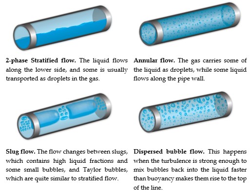
In three-phase flow (gas/oil/water), the behavior becomes even more intricate. The two liquids may mix to varying degrees, or the denser phase (usually water) may settle along the bottom of the line.
Among the flow regimes, stratified, annular, and dispersed bubble flows are generally unproblematic.
High gas velocities—achieved through elevated flow rates or reduced pipe diameters (relative to the mass flow)—can effectively "drag" liquid along the line. This helps minimize liquid buildup and reduce hydrostatic pressure.
However, increasing velocity also leads to greater frictional losses. A careful balance must be maintained between minimizing friction and preventing liquid accumulation.
Excess liquid buildup is the primary cause of slugging, a flow regime that is generally undesirable—especially if the slugs persist all the way to the outlet.
Slugging
Slug flow is characterized by alternating pockets of gas (Taylor bubbles) and liquid slugs. In vertical lines, Taylor bubbles are symmetrical and bullet-shaped. In inclined or horizontal lines, they travel along the upper section with a liquid film beneath. Some gas will also be dissolved in the liquid, and some droplets may also travel in the gas.
Hydrodynamic slugs form when surface waves on the liquid grow large enough to fill the pipe. Steady-state simulation programs are most suited to studying this type of slugs. Hydrodynamic slugs can cause:
- Sudden, large liquid surges at the outlet, risking plant flooding.
- Strong reaction forces, especially in bends.
- Increased sand production in certain wells.
- Maintain high enough gas velocity to prevent liquid accumulation.
- Balance velocity to avoid excessive friction losses.
Estimating Slug Lengths
Equations exist to estimate hydrodynamic slug lengths. One example is Scott’s equation, illustrated below:
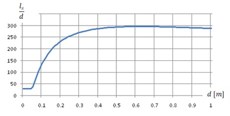
According to Scott’s model:
- A 0.5 m ID pipe may experience average slug lengths of ~150 m
- A 0.25 m ID pipe may see ~63 m slugs
- Maximum slug lengths may reach 4 to 5 times the average
Using Scott's model (and various other models) is straightforward. However, since hydrodynamic slugs are not the worst-case scenario and empirical slug length models tend to be unreliable, FlowlineProSS does not include slug length estimates.
For detailed analysis, use FlowlineProTransient.
Terrain Slugging
Terrain slugging is often more severe. It occurs when liquid accumulates in low-lying sections of a flowline, well, or riser.
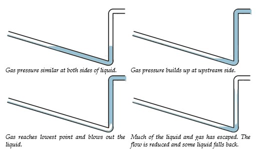
Note: The uphill section doesn’t need to be steep. Any geometry that allows liquid to settle during low gas flow can produce long terrain slugs—potentially as long as the low-lying segment itself.
While transient simulation is required for accurate slug length prediction, studying the geometry can offer valuable early-phase clues into worst-case scenarios.
Operational Slugging
Slugging can also be triggered by flowline operations:
- Pigging pushes liquid ahead of the pig as a slug
- Shutdowns drain liquid to low points; restart may eject it as a slug
- Flow rate changes alter liquid fractions, potentially forming large slugs
Hydrates
Gas hydrates are a major concern in subsea flow assurance.
These ice-like crystals form when gas molecules interact with water under specific pressure and temperature conditions—often well above freezing.
Hydrate formation requires attention in nearly all subsea multiphase flow projects.
Hydrates can:
- Restrict flow
- Cause complete blockages
- Be extremely difficult and risky to remove once formed
- Accurate fluid composition data.
- Reliable thermal and flow simulations.
- Effective countermeasures (e.g., inhibitors, insulation, heating).
- Sound operational procedures.
- A strategy for removing hydrate plugs if they form despite efforts to avoid them.
FlowlineProSS predicts pressure, temperature, and residence time for gas, oil, and water—critical for evaluating hydrate risk, especially when relying on kinetic inhibitors with time-limited effects. These results are then used together with data from the hydrate file to plot where hydrate formation can be expected.
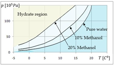
The plot above shows how pressure and temperature affect hydrate formation. Additives like methanol or MEG shift the hydrate boundary, allowing safer operation at lower temperatures or higher pressures.
Electric or hot water heating is sometimes used, but for long lines, chemical injection is usually more practical.
Simulations often involve generating multiple PVT and hydrate tables for different inhibitor concentrations. Hydrate temperatures can be plotted against pressure, or vice versa.
Due to uncertainties in input data, sea temperature variation, and uneven inhibitor distribution, safety margins are essential.
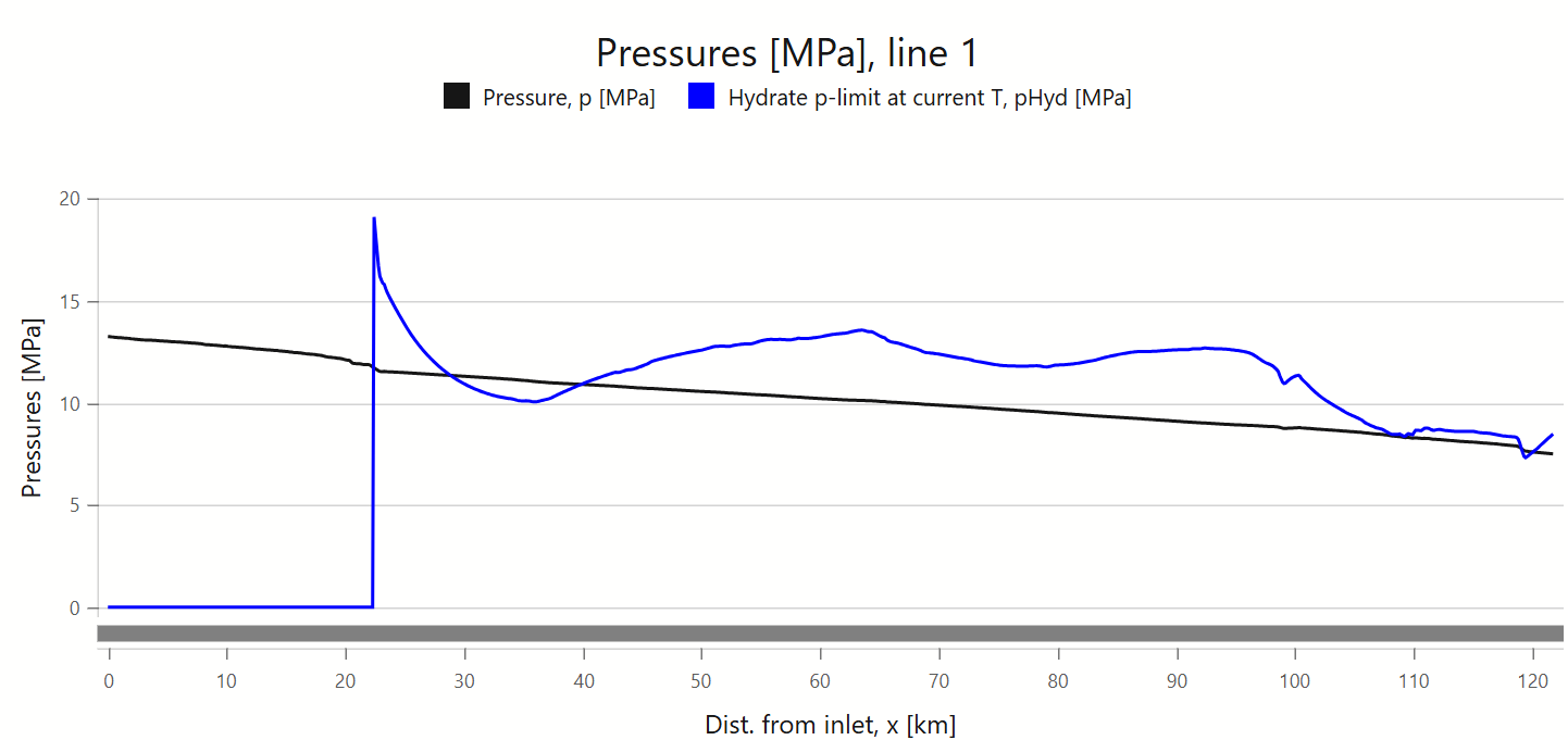
The figure above shows a pressure profile along a flowline, alongside the hydrate formation pressures—calculated based on the temperature predicted by FlowlineProSS at each point along the line.
Near the inlet, the fluid is relatively hot, and hydrate formation would require pressures higher than those listed in the hydrate reference file. As a result, the first 22 km appears as a flat line.
Around 29 km into the flowline, the hydrate formation pressure drops below the actual pressure, indicating that hydrates would begin to form.
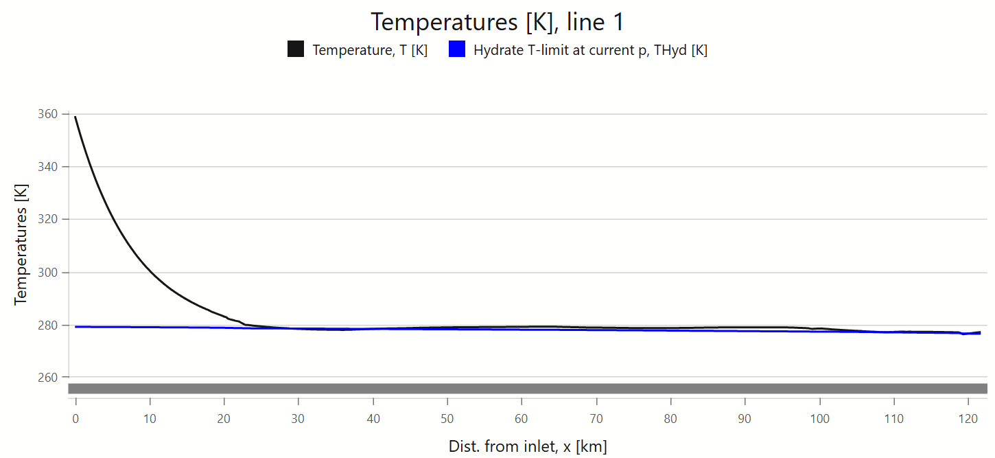
The next figure presents the same information from a different perspective: it plots the actual fluid temperature and the hydrate formation temperature (based on line pressure) along the flowline.
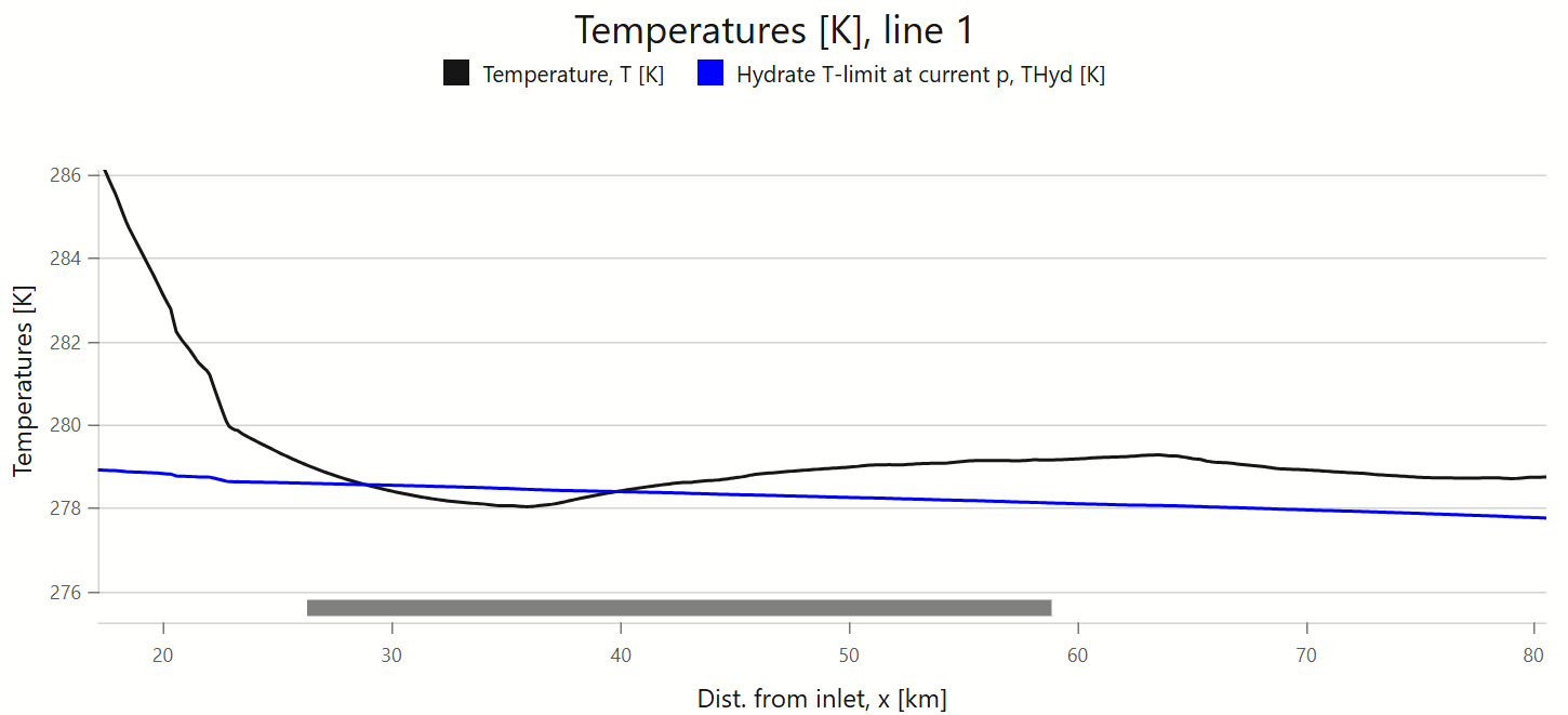
Due to the high inlet temperature, the plot scales to make the two lines almost overlap for most of the line. Zooming into specific regions—such as the one shown below—provides clearer insight.
Further discussion of hydrate prevention is available in Pipe Flow 2, Ref. [2].
Hydrate Plug Removal
Since hydrates tend to form at high pressure and low temperature, heating, pressure reduction or chemical injection should, in principle, solve the problem. But all of those methods are usually difficult to apply in practice once the line is blocked by a hydrate plug:
- The blockage means it is too late to add more chemicals—they cannot be transported from the injection point to the plug.
- Adding additional heating requires electrical or other heating to have been installed from the start.
- Heating from the outside of the line is also very difficult. It would require locating the hydrate plug accurately and then somehow installing temporary heating around the line.
- Reducing the pressure is often the best option, but it requires pressure reduction on both sides of the plug.
- If the plug comes loose when the pressure is uneven, it may be propelled violently and cause severe damage.
- During the design phase, it is wise to consider how to reduce pressure on both sides if a hydrate plug ever forms.
Other Chemical Challenges
Depending on fluid composition, additional issues may arise, including:
- Waxes
- Asphaltenes
- Scales
- Corrosion
- Erosion
- Particle buildup
These topics are also covered in Pipe Flow 2, Ref. [2].
Pressure Surges & Cavitation
Pressure surges are mostly a concern in single-phase liquid systems. They are highly transient and described in detail in Pipe Flow 1.
Steady-state simulations are not suitable for modeling pressure surges, but they are rarely a concern in multiphase flowlines.
Cavitation occurs when pressure drops low enough to cause liquid boiling, followed by violent bubble collapse. This can erode components like chokes, but it’s not typically a problem in the flowlines themselves.